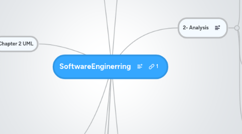
1. 4. Object Design(ch8+9)
1.1. Reuse
1.1.1. Reuse
1.1.1.1. White Box
1.1.1.1.1. Implmentation inheritence
1.1.1.1.2. Specification inheritence
1.1.1.2. Black Box
1.1.1.2.1. Delegation
1.1.1.3. Frameworks
1.1.1.3.1. White box
1.1.1.3.2. Black box
1.1.1.4. Concepts
1.1.1.4.1. Inheritence, Abstract methods, Interfaces
1.1.1.5. Select Design patterns
1.1.1.5.1. Bridge pattern
1.1.1.5.2. Adapter pattern
1.1.1.5.3. Strategy pattern
1.1.1.5.4. Abstract Factory pattern
1.1.1.5.5. Composite pattern
1.1.1.5.6. Facade pattern
1.1.2. Interface Specification
1.1.2.1. of the subsystem services
1.1.2.2. Role of developers
1.1.2.3. Contracts
1.1.2.3.1. Invariant
1.1.2.3.2. postcondition
1.1.2.3.3. precondition
1.1.2.3.4. OCL
1.2. Model>Code
1.2.1. Restructuring
1.2.2. Optimistaion
1.3. OUTPUTS:
1.3.1. Object design model
1.3.1.1. Class Diagram
2. 5.Implementation
2.1. Activities
2.1.1. Optimisation
2.1.2. Realizing associations
2.1.3. mapping constracts to exceptions
2.1.4. Class models > Storage schema
2.2. Types of transformations
2.2.1. Model transformation
2.2.2. refactoring
2.2.3. forward engineering
2.2.4. reverse engineeringh
3. 6.Testing
4. Chapter 1
4.1. What is software enginering
4.1.1. Modeling
4.1.2. Problem solving
4.1.3. knowledge acquisition
4.1.4. rationalle
4.2. Software engineering concepts
4.2.1. Participents and roles
4.2.2. Systems and models
4.2.3. functional and nonfunctional requirements
4.3. Software engineering activities
4.3.1. ch4-5-6-7-8-9
5. Chapter 2 UML
5.1. Diagrams
5.1.1. Activity diagrams
5.1.2. StateMachines
5.1.3. Interaction diagrams
5.1.4. Class diagrams
5.1.5. Use Case Diagrams
5.2. Concepts
5.2.1. Data types
5.2.2. Class Types
5.2.3. Abstract Classes
5.2.4. OOP Modeling
5.2.4.1. Application domain
5.2.4.2. Solution domain
5.2.5. falsification and modeling
6. Chapter 3
6.1. Project organisations
6.1.1. heirachal
6.1.2. liasion
6.1.3. peer
6.1.4. roles
6.1.4.1. developer
6.1.4.1.1. What each of these guys do. examples
6.1.4.2. liasion
6.1.4.3. manager
6.1.4.4. consultant
6.1.4.5. Participatiation
6.1.4.5.1. 1-1,1-few, many to many
6.1.5. What should a project organisation define
6.2. A Project
6.2.1. Deliverables
6.2.2. schedules
6.2.3. activity
6.2.4. resource
6.2.5. -
6.2.5.1. task specified by work package(completion criteria, risks,description)
6.2.5.1.1. activity = large unit
6.3. communication mechanisisms
6.3.1. synchronous
6.3.1.1. hallway/meeting(smokesignals)
6.3.2. asynchronous
6.3.2.1. email / newsgroup / portal
6.4. organisationl activities
6.4.1. join team
6.4.2. join communication infrastructure
6.4.3. attend status meetings
6.4.4. organise client and project reviiews
6.5. communication Event
6.5.1. planned communication
6.5.1.1. problem definition
6.5.1.2. project review
6.5.1.3. client review
6.5.1.4. status review
6.5.1.5. release
6.5.1.6. postmortom
6.5.2. unplanned commmunication
6.5.2.1. requrest for clarificaiton /change
6.5.2.2. issue resolution
7. Models
7.1. Functional Model
7.1.1. use case, user POV, from req elicitation.
7.2. Object Model
7.2.1. during analysis it is the analysis object model
7.2.1.1. Class diagram
7.2.2. during system design is is the system design object model
7.2.2.1. includes subsystem interface stuff
7.2.3. during objject design it is the object design model
7.2.3.1. includes detailed descriptions of solution objects
7.3. Dynami Model
7.3.1. interaction,state,actuvuty
8. Requirements Elecititation
8.1. Concepts
8.1.1. Requirements Validation
8.1.1.1. complete,consistent,unambigious,correct,ralistic,verifiable,traceable
8.1.2. Types of Req. Elicitation.
8.1.2.1. Greenfield Engineerying
8.1.2.2. ReEngineering Project
8.1.2.3. Interface Envineering
8.1.3. Quality Requirements
8.1.3.1. Usability, Robustness, Availablility
8.1.4. Types of Requirements
8.1.4.1. Functional Requirements
8.1.4.2. NonFunctional Requirements
8.1.4.2.1. techniques to elicit rewuirements
8.2. Activities.
8.2.1. Identify actors
8.2.2. Identify Scenarios
8.2.2.1. AsIs / Visionary / Evaluation / Training
8.2.2.2. How to find them
8.2.2.2.1. Questions to ask,
8.2.2.2.2. Examplse of them
8.2.3. Identifying Use Cases
8.2.3.1. Section of textual ones
8.2.3.1.1. Exceptios
8.2.4. Use Case Diagrams
8.2.4.1. Identifying Use Cases
8.2.4.2. Refining use cases
8.2.4.2.1. Go Back to client
8.2.4.3. Identifying relations+actors between actors + use cases
8.2.4.3.1. Communication
8.2.4.3.2. extend
8.2.4.3.3. include
8.2.5. Identify Initial Analysis Objects
8.2.5.1. Participation objects for each use case
8.2.6. Identify NonFunctional Requirements
8.2.6.1. FURPS
8.2.6.1.1. Functionality
8.2.6.1.2. Usability
8.2.6.1.3. Reliability
8.2.6.1.4. Performance
8.2.6.1.5. Supportability
8.3. Management
8.3.1. JAD
8.3.2. Tracability maintainance
8.3.3. Documentation
8.4. OUTPUTS:
8.4.1. NonFunctional Requirements
8.4.2. Functional Model
8.4.2.1. Use Case Diagrams
9. 2- Analysis
9.1. Analysis Objject Model
9.1.1. Steps to get objects
9.1.1.1. Identify Classes, Attributes, Associations and operations generalisation + specialization + aggregations
9.1.1.2. types
9.1.1.2.1. Entity, Boundary, Control (=how to identify?)
9.1.2. Approaches
9.1.2.1. Application domain approach (x)
9.1.2.2. Syntactic Approach (Y)
9.1.2.2.1. Find participating objects (how)
9.1.2.2.2. look at verbsd nouns
9.1.2.3. design pattern approach(x)
9.1.2.4. component based approach(x)
9.2. Dynamic Model
9.2.1. Sequence Diagram(Iteration)
9.2.1.1. Fork and Stair
9.2.2. Communication diagram (sequence diagram derivitave)
9.2.3. StateChart Diagram
9.2.3.1. events,transitions, AND
9.3. OUTPUTS:
9.3.1. Analysis Object Model
9.3.1.1. Class Diagram
9.3.2. Dynamic Model
9.3.2.1. Sequence Diagram
9.3.2.1.1. DYNAMIC CONNDTION = same methods in sequence and class diagrams
9.3.2.2. statechart
10. 3. Ssytem Design(ch6+7)
10.1. OUTPUTS:
10.1.1. Design Goals
10.1.2. Subsystem Decomposition
10.1.2.1. software arfhecdihne
10.1.3. Object Design Model
10.2. Decompose the system
10.2.1. Subsystems
10.2.2. Services and subsystem interfaces
10.2.3. ball+socket notatio
10.2.4. Coupling and Cohesion
10.2.5. Architectural styles(decomp methods)
10.2.5.1. Layers and Parittions
10.2.5.1.1. Open/Closed
10.2.5.2. Repository
10.2.5.3. MovelViewController(x)
10.2.5.4. Client/Server
10.2.5.5. Peer to Peeer
10.2.5.6. 3 Tier
10.2.5.7. Pipe and Filter(x)
10.2.5.8. the Software Architecture IS a architectural style, which is a way of decomposing a systems
10.3. Identify design goals
10.3.1. Format
10.3.2. Perfofmance, dependability,cost,maintainability
10.3.3. Trade off's
10.4. Addressing Design Goals
10.4.1. Prototypes
10.4.2. Map Subsystems to Nodes
10.4.3. Identify persistant data ( types of db)
10.4.3.1. flatfile
10.4.3.1.1. good for lots of small data but bad for concurrency
10.4.3.2. relational dv
10.4.3.2.1. good for lots of data + concurrancy but bad for small sets of data
10.4.3.3. OOP DB
10.4.3.3.1. good for irregular associations, medium size, but slow.
10.4.4. Provide access controll (X)
10.4.5. Design Global control flow
10.4.5.1. Implicit
10.4.5.2. Explicit
10.4.5.2.1. Centeralised control(FORK)
10.4.5.2.2. decenteralised control(STAIR)
10.4.5.3. 2 things are inheritly concurrent if they can recieve 2 things at the saemt times without interacitng
10.4.5.4. synchronous and asynchronus messages (reply ot not in sequence diagram)
10.4.6. REVIEW it to ensure correct,complete,consistant,realistic, readable
10.4.7. boundary condiutions
10.4.7.1. INCLUDE 3 more circles, STARTUP,SHITDOWN,CONFIGURE
10.4.7.2. exception handingling
10.4.7.2.1. EXCEND error
