

1. Tomography
1.1. Definition: specialized technique for producing radiograph of only a slice of the patient
1.1.1. Each Tomograph has focal trough:3d Image layer tissue in this section sharply defined and in focus and revealed clearly in final image
1.1.2. Focal plane level: height of focal plane above table
1.1.3. structures outside are blurred
1.2. Clinical Applications
1.2.1. 1. Assessment of jaw height, thickness and texture before inserting implant1.
1.2.2. 2.Postoperative evaluation of implants
1.2.3. 3. Assessment of the size, position and extent of antral tumours
1.2.4. 4. Evaluation of grossly comminuted facial fractures to determine all the fracture sites
1.2.5. 5. Assessment of the extent of orbital blow-out fracture
1.3. Movements
1.3.1. Linear • Circular • Elliptical • Spiral • Hypocycloida
1.4. Tomographic angle
1.4.1. GREAT angle = thin section; more than 10 = used in high contrast bone
1.4.2. narrow angle = thick section upto 25mm ;less than 10= zonography in low contrast soft tissue = zonography
1.5. Machine
1.5.1. X ray tube
1.5.2. xray film under table
1.5.3. rigid connector between them rotates around fulcrum
2. CT
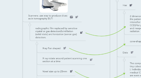
2.1. Scanners: use xray to produce slices as in tomography BUT:
2.1.1. radiographic film replaced by sensitive crystal or gas detectorsScintillation (solid state) and Ionization (xenon gas) detectors.
2.1.1.1. Xray Fan shaped
2.1.1.2. X ray rotate around patient scanning one section at a time
2.1.1.3. Voxel size up to 25mm
2.1.1.4. No Reformatted Cuts
2.2. System Components
2.2.1. Gantry:
2.2.1.1. circular device that houses the Data Acquisition system (DAS) = Tube, Detectors, Filters, Collimators & Analog-to – Digital Converter (ADC)
2.2.1.1.1. Detector:Function as image receptors for remnant radiation, then converts the measurement into an electrical signal proportional to the radiation intensity. Two basic detector types are used: Scintillation (solid state) and Ionization (xenon gas) detectors.
2.2.2. Computer:
2.2.2.1. functions: 1. Control of data acquisition
2.2.2.2. 2. Image reconstruction
2.2.2.3. 3. Storage of image data
2.2.2.4. 4. Image display
2.2.3. Table
2.2.3.1. Automated device linked to the computer and gantry Designed to move in increments after every scan according to the technologists scan program
2.2.4. Operator's Console
2.3. Indications
2.3.1. Investigation of intracranial disease including tumours, haemorrhage and infarcts
2.3.2. Investigation of suspected intracranial and spinal cord damage following trauma to the head and neck
2.3.3. Assessment of fractures involving:
2.3.3.1. The orbits and naso-ethmoidal complex
2.3.3.2. The cranial base
2.3.3.3. The odontoid peg
2.3.3.4. The cervical spine
2.3.4. Tumour staging―assessment of the site, size and extent of tumours, both benign and malignant, affecting:
2.3.4.1. The maxillary antra
2.3.4.2. The base of the skull
2.3.4.3. The pterygoid region
2.3.4.4. The pharynx
2.3.5. Investigation of tumours and tumour-like discrete swellings both intrinsic and extrinsic to the salivary glands
2.3.6. Investigation of osteomyelitis
2.3.7. investigation of the TMJ
2.3.8. Preoperative assessment of maxillary and mandibular alveolar bone
2.3.9. height and thickness before inserting implants.
2.4. Advantages
2.4.1. Very small amounts, and differences, in X-ray absorption can be detected. This enables:
2.4.1.1. Detailed imaging of intracranial lesions
2.4.1.2. Imaging of hard and soft tissues
2.4.1.3. Excellent differentiation between different types of tissues, both normal and diseased
2.4.2. Images can be manipulated
2.4.3. Axial and coronal tomographic sections of the skulls are obtainable
2.4.4. Reconstructed images can be obtained from information obtained in the axial plane
2.4.5. images can be enhanced by the use of IV contrast media providing additional information.
2.5. Disadvantages
2.5.1. Expensive Equipment
2.5.2. Not Available
2.5.3. High Radiation Dose
2.5.4. Risk with IV Contrast agent
2.5.5. Metallic artifact
3. CBCT
3.1. Defenition:It is a recent imaging technique
3.1.1. Has
3.1.1.1. 2 dimensional detector area that rotate around the patient to acquire multiple 2D image intensifier tube/ Charged couple device (IIT/ CCD)Flat panel detectors have high resolution and inexpensive, but they require more radiation 
3.1.1.2. cone-shaped X-ray beam
3.1.2. Data
3.1.2.1. The computer then collect the information into tiny cubed or voxels (typically 0.4 mm x 0.4mm ). Individual voxels are much smaller than in medical CT. The voxel sizes in newer machines are even smaller (0.15mm x 0.15mm x 0.15 mm) so improving image resolution 
3.1.2.2. Over CT ,CBCT provides also reformatted panoramic cuts, transaxial( cross section cuts)
3.1.3. Final Image
3.1.3.1. The raw digital data is composed of multiple images resembling lateral ceph. each slightly offset from one another.
3.1.3.2. This data is reconstructed by computer algorithm to create volumetric data.
3.1.3.3. Multiple projections are acquired by rotational scanning to produce volumetric data from which multi-planar images can be generated.The volumetric data is presented on the computer screen as secondary images in three orthogonal planes (axial, sagittal , and coronal ) as well as 3D images
3.1.4. Field of View
3.1.4.1. Fields of view FOV FOV depend on: Detector size and shape Collimation of 1ry x- ray beam The larger the FOV the larger the voxel size, the lower the resolution.
3.1.5. Scanning the entire cranio-facial region is difficult because of high cost of large detectors. ➢Possible to increase the height of the FOV by using 2 scans one above the other and (stitching) the data
3.1.6. CBCT Multi-planar Reconstruction
3.1.6.1. Since the volumetric data is isotropic,means having properties that are identical in all directions ➢ Thus, data can be sectioned non-orthogonally (e.g. oblique, curved planar).
3.2. Advantages
3.2.1. Less radiation dose to the patients than CT (96 to 51% of CT)
3.2.2. Less expensive equipment than CT
3.2.3. Smaller in size than CT
3.2.4. Less scanning time than CT because it captures the necessary data in one rotation
3.2.5. Reformatted images can generate ● Panoramic ● Lateral cephalometric ● PA cephalometric ● Submentovertex
3.2.6. Sub-millimeter voxel resolution (0.4x0.4x0.4mm - 0.125x0.125x0.125mm). One scan contains more than 100 million voxels.
3.2.7. Interactive analysis for surgeries and implants 
3.3. Disadvantages
3.3.1. Poor soft tissue contrast (TMJ disc cannot be seen)
3.3.2. Patients have to remain stationary
3.3.3. Computer reconstructed panoramic images are not directly comparable with conventional panoramic radiographs.
3.3.4. Metallic objects produce streak artifacts.
3.4. Applications
3.4.1. Dental Implant
3.4.1.1. CBCT, combined with customized software, provide the necessary 3-D information. This allows determination of the optimal implant size and location considering surgical, anatomic, and prosthodontic issues.
3.4.1.2. Stereolythographic models of the jaws as well as surgical guides. Such models of the facial bones are used for pre-surgical treatment planning The surgical guides assist the clinician in precisely aligning the drill bits with respect to the jawbones to assure proper orientation and depth of the drill holes. 
3.4.2. Maxillofacial surgery
3.4.2.1. CBCT delineate the location, size and extension of intra bony lesion. This will give surgeon the needed information for surgical planning with ability to provide volumetric analysis of the case.
3.4.3. Temporomandibular joint
3.4.3.1. The TMJ is difficult to image with conventional techniques because of superimposition. CBCT provided valuable images of the osseous components of the TMJ such as osteophytes, erosion, fractures, ankylosis, or developmental abnormalities, as well as to evaluate the position of the condyle in the fossa in open-mouthed and closed-mouth positions. 
3.4.4. Orthodontics
3.4.4.1. CBCT providing 2D and 3D cephalometric images which is more accurate than conventional 2D cephalometric radiographs ( no magnification or parallax distortion). Distortion free panoramic reformatted image can be held without re expose the patient. 
3.4.4.2. Pharyngeal air way space and soft tissue relationship can be provided by CBCT. CBCT can detect teeth impaction easily.
3.4.5. Disease
3.4.5.1. Example Fibrous Dysplasia
3.4.6. Cleft palate
3.4.6.1. CBCT showed 3D relations of the defect and Cleft palate bone thickness around the existing teeth in proximity to the cleft. The volume of the graft material needed for repair could be estimated by volumetric analysis.
3.4.7. Endodontic application
3.4.7.1. Diagnosis of endodontic pathosis Canal morphology
3.4.7.2. Assessment of pathosis of non-endodontic origin Evaluation of root fractures and trauma
3.4.7.3. Analysis of external and internal root resorption and invasive cervical resorption
3.4.7.4. Pre-surgical planning
4. MRI
4.1. Defeniton
4.1.1. MRI is a technique that is used to create sectional pictures of the soft tissues of the human body as if it was cut in slices (tomography ) It is based on the application of strong magnetic fields followed by pulses of radio waves (Radiofrequency RF), and observing its effect on the tissues at a nuclear level (Nuclear Magnetic Resonance Imaging –NMRI)
4.1.2. MRI totally replaces conventional X-ray- generating equipment and film. Essentially it involves the behavior of protons in a magnetic field.
4.2. T1/T2
4.2.1. T1 Decay Longitudinal Relaxation NORMAL ANATOMY
4.2.1.1. Fluids have a long T l (i.e. they take a long time to re-establish their longitudinal magnetic moment), produce a weak signal and appear DARK
4.2.1.2. fat behaves in the opposite manner and has a short Tl, produces a strong signal and appears WHITE T1 is defined as the time it takes for the longitudinal magnetization 
4.2.2. T2 Decay Transverse Relaxation Show DISEASE
4.2.2.1. Fluids such as CSF have a long T2 (i.e. they dephase slowly) and give a strong signal and appear WHITE
4.2.2.2. Fat has a short T2, produces a weak signal and appears DARK 
4.3. Advantages
4.3.1. Ionizing radiation is not used
4.3.2. ➢ No adverse effects
4.3.3. ➢ Image manipulation
4.3.4. ➢ High resolution images in all planes
4.3.5. Excellent differentiation between different soft tissues
4.3.6. ➢ Excellent differentiation between normal and abnormal tissues.
4.4. Disadvantages
4.4.1. ➢ Bone does not give an MR signal, a signal is only obtainable from bone marrow
4.4.2. ➢ Scanning time can be long
4.4.2.1. ● motion artifacts
4.4.2.2. ● demanding on the patient
4.4.3. ➢ It is contraindicated in patients with
4.4.3.1. ● surgical clips
4.4.3.2. ● cardiac pacemakers
4.4.3.3. ● cochlear implants
4.4.3.4. ● first trimester of pregnancy
4.4.4. Equipment tends to be claustrophobic and noisy
4.4.5. ➢ Equipment is very expensive
4.4.6. ➢ Facilities are not widely available
4.5. Indications
4.5.1. Assessment of intracranial lesions particularly those involving ● posterior cranial fossa ● pituitary gland ● spinal cord
4.5.2. TMJ Investigations to show the soft tissue components of the joint including the disc position. MRI may be indicated: • When doubting internal derangement • Preoperatively before disc surgery.
4.5.3. Anterior Disc Displacement
4.5.4. Rheumatoid Arthritis
4.5.5. Tumour staging ● site ● size ● extent
4.5.6. Fracture + Haemosinus