

1. Activity Diagram
1.1. Classification
1.1.1. UML behavioral diagram
1.1.2. Dynamic system representation
1.2. Purpose
1.2.1. Model activity flows
1.2.2. Visualize processes
1.3. When to use activity diagramm
1.3.1. Use case analysis
1.3.1.1. Identify candiadate use cases
1.3.1.2. Define pre/post conditions
1.3.1.3. Model workflows between use cases
1.3.1.4. Model workflows with in use cases
1.3.2. Business process modeling
1.3.2.1. Coordinate activities
1.3.2.2. Represent business workflows
1.3.3. Complexity management
1.3.3.1. Handle multiple abstraction levels
1.3.3.2. Model complex operations
1.3.3.3. Detail high-level activities
1.3.4. Event coordination
1.3.4.1. Show relationship between events
1.3.4.2. Handle overlapping activities
1.4. Activity diagram notation
1.4.1. Primary elements
1.4.1.1. Activity -> set of actions
1.4.1.2. Action -> Single task
1.4.1.3. Object node -> object in flow
1.4.2. Flow controls
1.4.2.1. Control flow -> execution sequence
1.4.2.2. Object flow -> object movement
1.4.3. Boundaries
1.4.3.1. Initial node -> start point
1.4.3.2. Activity final node -> end point
1.4.4. Decision points
1.4.4.1. Decision node -> path selection
1.4.4.2. Merge node -> path convergence
1.4.5. Parallel processing
1.4.5.1. Fork node -> split into parallel flows
1.4.5.2. Join node -> synchronize parallel flows
1.4.6. Organization
1.4.6.1. Swimlane -> group by actor/thread
1.5. Example
2. Sequence Diagram
2.1. Difinition
2.1.1. Interaction diagrams
2.1.2. Detail operation execution
2.1.3. Object collaboration visualization
2.1.4. Time-focused representation
2.1.5. Vertical axis represents timme
2.2. What they capture
2.2.1. Use case realizations
2.2.2. Instance or generic diagrams
2.2.3. High-level interaction
2.3. Purpose
2.3.1. Model object interactions
2.3.2. Visualize message sequence
2.3.3. Show collaboration paths
2.3.4. Document system behavior
2.4. Sequence Diagram Notation
2.4.1. Participants
2.4.1.1. Actor
2.4.1.1.1. External entity interacting with subject
2.4.1.1.2. Represents a role, not physical entity
2.4.1.1.3. Can be human users or external hardware
2.4.1.2. Lifeline
2.4.1.2.1. Individual participant in interaction
2.4.1.2.2. Vertical line showing existence over time
2.4.2. Execution
2.4.2.1. Activations
2.4.2.1.1. Rectangle on lifeline
2.4.2.1.2. Period of operation performance
2.4.2.1.3. Aligned with start/end times
2.4.3. Messages
2.4.3.1. Basic Messages
2.4.3.2. Reflexive Messages
2.4.3.3. Lifecycle Messages
2.4.3.4. Timing
2.4.4. Documentation
2.4.4.1. Note
2.5. Example
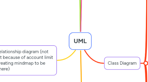
3. Entity relationship diagram (not UML but because of account limit when creating mindmap to be placed here)
3.1. Definition
3.1.1. Structure diagram for database design
3.1.2. Visualizes system structure
3.2. Core components
3.2.1. Entities
3.2.2. Relationships
3.2.3. Connecting sysbols
3.3. Purpose
3.3.1. Database design
3.3.2. Visualize system structure
3.3.3. Show inter-ralationship between entities
3.4. When to use entity relationship diagram
3.4.1. Database design
3.4.1.1. Plan changes safely
3.4.1.2. Visualize design concepts
3.4.1.3. Identify design concepts
3.4.1.4. Make corrections before implementation
3.4.1.5. Avoid production data risks
3.4.2. Database debugging
3.4.2.1. Understand complex schemas
3.4.2.2. Visualize entire database structure
3.4.2.3. Locate entities esily
3.4.2.4. View entities easily
3.4.2.5. Identify relationships
3.4.2.6. Analyze existing database
3.4.3. Database implementation
3.4.3.1. Automate database creation
3.4.3.2. Support patching processes
3.4.3.3. Transform diagrams to actual databases
3.4.4. Requirements engineering
3.4.4.1. Gather systemm requirements
3.4.4.2. Create conceptual models
3.4.4.3. Depict high-level business objects
3.4.4.4. Evolve into physical database models
3.4.4.5. Support process mapping
3.4.4.6. Facilitate data flow modeling
3.5. ERD notations
3.5.1. Basic components
3.5.1.1. Entity
3.5.1.1.1. Definable thing or concept
3.5.1.1.2. Represented as rounded rectangle
3.5.1.1.3. Exaples: person, object, concept, event
3.5.1.1.4. Like a database table
3.5.1.1.5. Show with name on top
3.5.2. Attributes
3.5.2.1. Entity attributes
3.5.2.1.1. Properties of entities (columns)
3.5.2.1.2. Have names and data types
3.5.2.1.3. Listed in entity body
3.5.3. Keys
3.5.3.1. Primary key (PK)
3.5.3.1.1. Uniquely identitfies records
3.5.3.1.2. Must contain unique values
3.5.3.1.3. No duplicates allowed
3.5.3.2. Foreign key (FK)
3.5.3.2.1. References a PK in another table
3.5.3.2.2. Used to define relationships
3.5.3.2.3. Can have duplicate values
3.5.4. Relationships
3.5.4.1. Connects between entities
3.5.4.2. Show as connectors
3.5.4.3. Define associations
3.5.5. Cardinality
3.5.5.1. Ont-to-one (1:1)
3.5.5.1.1. Used to split entities
3.5.5.1.2. Each record relates to exactly one record
3.5.5.2. One-to-many (1:M)
3.5.5.2.1. One entity instance links to many in another
3.5.5.2.2. Most common relationship type
3.5.5.3. Many-to-many (M:N)
3.5.5.3.1. Many instances link to many others
3.5.5.3.2. Split into two 1:M relationships in physical ERD
3.6. ERD modeling levels
3.6.1. Conceptual data model
3.6.1.1. Highest abstraction level
3.6.1.2. Models business objects
3.6.1.3. Shows overall system picture
3.6.1.4. Used by business analysts
3.6.1.5. Features
3.6.1.5.1. Entity names
3.6.1.5.2. Relationships
3.6.1.5.3. Supports generalization
3.6.1.6. Excludes implementation details
3.6.2. Logical data model
3.6.2.1. Middle abstraction level
3.6.2.2. Detailed version of conceptual model
3.6.2.3. Defines columns explicitly
3.6.2.4. Adds operational entities
3.6.2.5. Platform-independent
3.6.2.6. Features
3.6.2.6.1. Entity names
3.6.2.6.2. Relationships
3.6.2.6.3. Columns
3.6.2.6.4. Optional column types
3.6.3. Physical data model
3.6.3.1. Lowest abstraction level
3.6.3.2. Actual database blueprint
3.6.3.3. DBMS-specific design
3.6.3.4. Used by database engineers
3.6.3.5. Features
3.6.3.5.1. Entity names
3.6.3.5.2. Relationships
3.6.3.5.3. Columns
3.6.3.5.4. Column types/constraints
3.6.3.5.5. Primary keys
3.6.3.5.6. Foreign keys
3.6.3.5.7. DBMS-specific conventions
3.7. How to draw an ERD
3.7.1. Define Purpose
3.7.1.1. Determine modeling level needed
3.7.1.1.1. Conceptual (business objects)
3.7.1.1.2. Logical (detailed design)
3.7.1.1.3. Physical (database creation)
3.7.1.2. Align detail level with intended audience
3.7.2. Establish Scope
3.7.2.1. Set clear boundaries
3.7.2.2. Identify system boundaries
3.7.2.3. Prevent redundant entities
3.7.2.4. Focus modeling efforts
3.7.3. Create Base Structure
3.7.3.1. Identify major entities
3.7.3.2. Draw primary entities first
3.7.3.3. Focus on core business objects
3.7.4. Add Details
3.7.4.1. Define entity properties
3.7.4.2. Add columns to entities
3.7.4.3. Specify attribute characteristics
3.7.5. Review & Enhance
3.7.5.1. Evaluate completeness
3.7.5.2. Check for missing data requirements
3.7.5.3. Add additional entities if needed
3.7.5.3.1. Transactional entities
3.7.5.3.2. Operational entities
3.7.5.3.3. Event entities
3.7.6. Define Relationships
3.7.6.1. Connect related entities
3.7.6.2. Specify proper cardinality
3.7.7. Normalize Design
3.7.7.1. Reduce data redundancy
3.7.7.2. Improve data integrity
3.7.7.3. Restructure entities as needed
3.7.7.4. Split repeating data into separate entities
3.7.7.5. Establish foreign key relationships
3.8. Example flow Class diagram
4. What is Unified Modeling Language (UML)
4.1. What is it
4.1.1. Standardized modeling language
4.1.2. Graphical notation system
4.1.3. For software and systems design
4.2. Core functions
4.2.1. Visualize
4.2.2. Document
4.2.3. Design
4.2.4. Specify
4.3. Used for
4.3.1. Software systems
4.3.2. Business modeling
4.3.3. System architecture
4.4. Key benefits
4.4.1. Team communication
4.4.2. Design exploration
4.4.3. Architecture validation
4.5. Foundation
4.5.1. Best engineering practices
4.5.2. Object-oriented principles
5. Why UML
5.1. Industry needs
5.1.1. Automate software production
5.1.2. Improve quanlity
5.1.3. Reduce costs
5.1.4. Sorten time-to-market
5.2. Business challenges
5.2.1. Managing complexity
5.2.2. Solving architectural priblems
5.2.2.1. Distribution
5.2.2.2. Concurrency
5.2.2.3. Security
5.2.2.4. Load balancing
5.2.2.5. Fault tolerance
5.2.3. Web development complexities
5.3. UML goals
5.3.1. Enable meaningfule visual modeling
5.3.2. Provide extensibility mmechanisms
5.3.3. Remain language-independent
5.3.4. Establish formal modeling foundation
5.3.5. Enable advanced concepts
5.3.5.1. Frameworks
5.3.5.2. Patterns
5.3.5.3. Components
5.3.6. Integrate best practies
6. UML - An Overview
6.1. Multiple viewpoints
6.1.1. Manu diagrams for different perspectives
6.1.2. Various stakeholders need different views
6.2. Key stakeholders
6.2.1. Analysts
6.2.2. Designers
6.2.3. Coders
6.2.4. Testers
6.2.5. QA
6.2.6. Customers
6.2.7. Techinical authors
6.3. Diagram types
6.3.1. Struture diagrams (static)
6.3.1.1. Class
6.3.1.2. Component
6.3.1.3. Deployment
6.3.1.4. Object
6.3.1.5. Package
6.3.1.6. Composite structure
6.3.1.7. Profile
6.3.2. Behavior diagrams (dynamic)
6.3.2.1. Use case
6.3.2.2. Activity
6.3.2.3. State machine
6.3.2.4. Sequence
6.3.2.5. Communication
6.3.2.6. Interaction overview
6.3.2.7. Timing
7. Class Diagram
7.1. Purpose
7.1.1. Show static structure of classifiers
7.1.2. Provide foundation for other UML structure diagrams
7.2. Components
7.2.1. Classes
7.2.2. Relationships between classes
7.3. What is class
7.3.1. Definition
7.3.1.1. Description of objects with similar roles
7.3.1.2. Template for group of similar objects
7.3.2. Components
7.3.2.1. Structural features (attributes)
7.3.2.1.1. Define waht objects "know"
7.3.2.1.2. Represent object state
7.3.2.1.3. Static characteristics
7.3.2.2. Behavioral features (operations)
7.3.2.2.1. Define what objects "can do"
7.3.2.2.2. Enable object interactions
7.3.2.2.3. Dynamic characteristics
7.4. Class Notation
7.4.1. Class name
7.4.1.1. Appears in first partition
7.4.1.2. Identifies the class
7.4.2. Attributes
7.4.2.1. Show in second partition
7.4.2.2. Format: name : type
7.4.2.3. Maps to member variables/data members
7.4.3. Operations (methods)
7.4.3.1. Show in third partition
7.4.3.2. Services provided by the class
7.4.3.3. Format: name(parameter: type) : return_type
7.4.3.4. Maps to class methods in code
7.4.3.5. Example
7.5. Class Relationships
7.5.1. Inheritance
7.5.1.1. "is-a" relationship
7.5.1.2. Solid line -> hollow arraw
7.5.1.3. Subclass -> parent
7.5.2. Simple association
7.5.2.1. Peer connection
7.5.2.2. Solid line
7.5.3. Aggregation
7.5.3.1. "part of" relationship
7.5.3.2. Unfilled diamond
7.5.3.3. Separate lifetimes
7.5.4. Composition
7.5.4.1. Strong "contains" relationship
7.5.4.2. Filled diamond
7.5.4.3. Dependent life times
7.5.5. Dependency
7.5.5.1. One-way impact
7.5.5.2. Dashed arraw
7.6. Visibility
7.6.1. Public
7.6.1.1. Accessible by all classes
7.6.1.2. Symbol: +
7.6.2. Private
7.6.2.1. Accessible only within class
7.6.2.2. Symbol: -
7.6.3. Protected
7.6.3.1. Accessible by class and subclasses
7.6.3.2. Symbol: #
7.6.4. Package
7.6.4.1. Accessible with in package
7.6.4.2. Symbol: ~
7.7. Multiplicity
7.7.1. Basic types
7.7.1.1. 1 -> Exactly one
7.7.1.2. 0..1 -> zero or one
7.7.1.3. * -> many (0..*)
7.7.1.4. 1..* -> one or more
7.7.2. Specific values
7.7.2.1. n -> exac number
7.7.2.2. n..m -> range
7.7.3. Complex
7.7.3.1. 0..1, 3..4, 6..* -> Selective values
7.8. Example
8. Use Case Diagram
8.1. Definition
8.1.1. System requirements representation
8.1.2. Show "what" not "how"
8.1.3. End user's prespective
8.2. Chracteristics
8.2.1. Simple structure
8.2.2. Few shapes (<20 cases)
8.2.3. External system interactions
8.3. Scope
8.3.1. Shows relationships
8.3.2. Omits step sequence
8.3.3. Functional requirements only
8.4. Limitations
8.4.1. No implementation details
8.4.2. No non-functional requirements
8.4.3. Requires complementary diagrams
8.5. Purpose
8.5.1. Development stage
8.5.1.1. Early development phase
8.5.1.2. Collaborative creation
8.5.2. System definition
8.5.2.1. Specify system context
8.5.2.2. Capture requirements
8.5.3. Architecture
8.5.3.1. Validate system architecture
8.5.4. Implementation
8.5.4.1. Drive development
8.5.4.2. Generate test cases
8.6. Components
8.6.1. Actor
8.6.1.1. Human/system interacting with use cases
8.6.1.2. Named by noun
8.6.1.3. Plays roles in business
8.6.1.4. Trigger use cases
8.6.1.5. Has reponsibilities and expectations
8.6.2. Use case
8.6.2.1. System function/process
8.6.2.2. Named by verb + noun
8.6.2.3. Must connect to actors
8.6.3. Comunication link
8.6.3.1. Connect actors to use cases
8.6.3.2. Solid line
8.6.3.3. Presents message exchange
8.6.4. System boundary
8.6.4.1. Defines scope
8.6.4.2. Can be entire system
8.6.4.3. Can be module-base for complex systems
8.7. Relationships
8.7.1. Extends
8.7.1.1. Optional behavior
8.7.1.2. Base case may inclide extension
8.7.1.3. Notation: dotted arraow
8.7.1.4. Direction: child -> base case
8.7.1.5. Example: "Invalid password" extends "login"
8.7.2. Include
8.7.2.1. Required behavior
8.7.2.2. Base case always includes child functionality
8.7.2.3. Notation: dotted arrow
8.7.2.4. Direction: base -> child case
8.7.3. Generalization
8.7.3.1. Parent-child relationship
8.7.3.2. Child enhances parent
8.7.3.3. Notation: solid arraw with triangle head
8.7.3.4. Direction: child -> parent