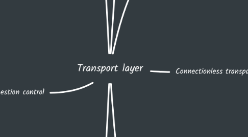
1. Connection-oriented transport: TCP
1.1. Segment structure
1.1.1. Source and dest port
1.1.2. Seq # and ACK # (cumulative)
1.1.3. Length, congestion notification and management
1.1.4. Flow control, checksum and TCP option
1.1.5. Application data
1.2. Reliable data transfer
1.2.1. Out-of-order segment handling up to implementor
1.2.2. EstimatedRTT = (1 - α) × EstimatedRTT + α × SampleRTT
1.2.3. TimeOutInterval = EstimatedRTT + 4 × DevRTT
1.2.4. DevRTT = (1 - β) × DevRTT + β × |SampleRTT - EstimatedRTT|
1.2.5. On 3 same ACKs, sender resend smallest unACKed segment
1.3. Flow control
1.3.1. Receiver advertises free buffer space in rwnd field
1.3.2. Sender limits window
1.4. Connection management
1.4.1. Sender/receiver handshake
1.4.1.1. Agree to enstablish connection
1.4.1.2. Angree on parameters
1.4.2. 3-way handshake
1.4.2.1. Client: LISTEN - SYNSENT - ESTAB
1.4.2.2. Server: LISTEN - SYNRCVD - ESTAB
2. Principles of congestion control
2.1. Scenario 1
2.1.1. One router, infinite buffers
2.1.2. Two flows, no retransmissions
2.1.3. Maximum per-connection throughput is R/2
2.1.4. Large delays as arrival rate approches R/2
2.2. Scenario 2
2.2.1. One router, finite buffers
2.2.2. Two flows with lost/timed-out retransmissions
2.2.2.1. Application-layer input = Application-layer output
2.2.2.2. Transport-layer input includes retransmissions
2.2.3. Idealization
2.2.3.1. Perfect knowledge
2.2.3.1.1. Sender knows when router buffers available
2.2.3.1.2. No retransmission needed
2.2.3.2. Some perfect knowledge
2.2.3.2.1. Sender know when pkt is dropped
2.2.3.2.2. As input approaches to R/2, some pkts retransmitted
2.2.3.3. Un-needed duplicates (realistic)
2.2.3.3.1. Sender can time-out prematurely and deliver copies
2.2.3.3.2. As input approaches to R/2, some retransmissions and un-needed duplicates
2.3. Scenario 3
2.3.1. 4 senders, multi-hop paths with timeout/retransmissions
2.3.2. When pkts dropped, upstream transmission capacity and buffering used is wasted
2.4. Approaches
2.4.1. End-end congestion control
2.4.1.1. No feedback from networks
2.4.1.2. Congestion inferred from observed loss, delay
2.4.1.3. Used in TCP
2.4.2. Network-assisted congestion control
2.4.2.1. Direct feedback to hosts
2.4.2.2. Indicates congestion level or set sending rate
2.4.2.3. Used in TCP ECN, ATM, DECbit
3. TCP congestion control
3.1. TCP AIMD
3.1.1. Additive increase
3.1.2. Multiplicative Decrease
3.1.2.1. Cut in half on triple duplicate ACK (TCP Reno)
3.1.2.2. Cut to 1 MSS on timeout (TCP Tahoe)
3.2. TCP sender limits transmission
3.2.1. TCP rate ≈ cwind / RTT
3.2.2. cwnd adjusted in response to network congestion
3.2.3. TCP slow start
3.2.3.1. Rate ramps up exponentially fast
3.2.3.2. Linear increase when cwnd gets half the value before timeout
3.3. TCP CUBIC
3.3.1. After cutting cwind in half on loss, initially ramp faster, then slower
3.3.2. Increases cwind as a cubic function
3.4. Delay-based approach
3.4.1. Keep bottolneck link busy but avoid delays/buffering
3.4.2. Uncongested trhoughput = cwind / minimum RTT observed
3.4.3. If mesured throughput close to uncongested one, increase cwind linearly, else decrease
3.5. Network-assisted approach
3.5.1. Network router marks two bits in IP header to indicate congestion
3.5.2. Indication to destination that notifies sender on ACK
4. Transport-layer services
4.1. Logical communication
4.1.1. Network layers connects hosts
4.1.2. Transport layer connects processes
4.1.2.1. Sender
4.1.2.1.1. Determines segment header
4.1.2.1.2. Creates segment
4.1.2.1.3. Passes to IP
4.1.2.2. Receiver
4.1.2.2.1. Checks header values
4.1.2.2.2. Extracts message
4.1.2.2.3. Demultiplexes message via socket
4.2. Protocols action in end systems
4.2.1. Sender breaks applications in segments
4.2.2. Receiver reassembles segments
4.3. Two protocols available
4.3.1. TCP (Transmission Control Protocol)
4.3.1.1. Reliable in-order delivery
4.3.1.2. Congestion control
4.3.1.3. Flow control
4.3.1.4. Connection setup
4.3.2. UDP (User Datagram Protocol)
4.3.2.1. Unreliable unordered delivery
4.3.2.2. No-frills extension of "best-effort" IP
5. Multiplexing and demultiplexing
5.1. Multiplexing at sender handles data from multiple sockets
5.2. Demultiplexing at receiver delivers segments to socket
5.2.1. Host receives IP datagrams
5.2.1.1. Source and destination IP address
5.2.1.2. Transport-layer segment with source and destination port number
5.2.2. Uses IP addresses and port numbers to direct segment to socket
5.2.2.1. Connectionless: uses only dest port
5.2.2.2. Connection-oriented: uses all 4 values
6. Connectionless transport: UDP
6.1. Connectionless
6.1.1. No handshaking between sender and receiver (no RTT)
6.1.2. Each UDP segment is indipendent
6.2. Smaller header, no congestion control, best effort service
6.3. Receiver checks UDP checksum header value
7. Principles of reliable data transfer
7.1. Reliable data transfer (rdt) protocol depend on the unreliable channer
7.2. rdt 1.0: reliable channel
7.3. rdt 2.0: channel with bit error
7.3.1. Checksum to detect bit errors
7.3.2. Receiver send ACKs or NAKs
7.3.3. Sender retransmits on NAK
7.3.4. Stop and Wait
7.3.4.1. t0 = 2tprop + 2tproc + nf/R + na/R
7.3.4.2. Reff = (nf - no) / t0
7.3.5. rdt 2.1: handling garbled ACK/NAK
7.3.5.1. Sender add seq #
7.3.5.2. Receiver discards duplicate
7.3.6. rdt 2.2: NAK-free protocol
7.3.6.1. Receiver include seq #
7.3.6.2. Duplicate ACK at sender is same as NAK
7.4. rdt 3.0: channel with error and loss
7.4.1. Sender use timeout for ACKs
7.4.2. Pipelining
7.4.2.1. Go-Back-N
7.4.2.1.1. Sender has a window of transmitted pkts and on timeout retransmit all from the unACKed
7.4.2.1.2. Receiver send ACK for in-order seq # and re-ACK for out-of-order pkt (discard or buffer)
7.4.2.1.3. Ws <= 2^m - 1
7.4.2.1.4. Tout = 2Tprop + Tproc + Tf + Tack
7.4.2.2. Selective Repeat
7.4.2.2.1. Receiver ACK correct received pkts
7.4.2.2.2. Sender times-out/retransmits the unACKed pkts in window
7.4.2.2.3. Ws + Wr <= 2^m
7.4.2.2.4. Per Pf -> 0, SR e GBN hanno la stessa efficienza
