

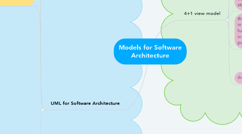
1. UML for Software Architecture
1.1. states that “the Unified Modeling Language (UML) is a graphical language for visualizing, specifying, constructing, and documenting the artifacts of a software-intensive system.”
1.2. UML offers a standard way to draw a system’s blueprints, including conceptual notions and system functions as well as concrete designs.
1.3. UML is a typical OO analysis and design notational tool that provides many useful diagrams can be used to map requirement specifications to architectural designs and to coding.
1.4. UML provides several modeling diagrams that can be grouped into two major categories:
1.4.1. Behavioral Diagram
1.4.1.1. Activity Diagram
1.4.1.1.1. It is a graphical representations of workflows of stepwise activities and actions with support for choice, iteration and concurrency
1.4.1.2. Use Case Diagram
1.4.1.2.1. It describes a system’s functional requirements in terms of use cases that enable you to relate what you need from a system to how the system delivers on those needs.
1.4.1.3. State Machine Diagram
1.4.1.3.1. It shows the discrete behavior of a part of a designed system through finite state transitions.
1.4.1.4. Sequence Diagram
1.4.1.4.1. It shows the sequence of messages exchanged between the objects needed to carry out the functionality of the scenario.
1.4.1.5. Communication Diagram
1.4.1.5.1. It shows interactions between objects and/or parts (represented as lifelines) using sequenced messages in a free-form arrangement.
1.4.1.6. Interaction Overview Diagram
1.4.1.6.1. It depicts a control flow with nodes that can contain other interaction diagrams.
1.4.1.7. Timing Diagram
1.4.1.7.1. It shows interactions when the primary purpose of the diagram is to reason about time by focusing on conditions changing within and among lifelines along a linear time axis.
1.4.2. Structural Diagrams
1.4.2.1. Composite Structure Diagram
1.4.2.1.1. It shows the internal structure of a classifier, classifier interactions with the environment through ports, or behavior of a collaboration.
1.4.2.2. Deployment Diagram
1.4.2.2.1. It shows a set of nodes and their relationships that illustrates the static deployment view of an architecture.
1.4.2.3. Package Diagram
1.4.2.3.1. It groups related UML elements into a collection of logically related UML structure.
1.4.2.4. Profile Diagram
1.4.2.4.1. Profile diagram is structure diagram which describes lightweight extension mechanism to the UML by defining custom stereotypes, tagged values, and constraints.
1.4.2.5. Class Diagram
1.4.2.5.1. It shows a set of classes, interfaces, and collaborations and their relationships, typically, found in modeling object-oriented systems.
1.4.2.6. Object Diagram
1.4.2.6.1. It shows a set of objects and their relationships, which is the static snapshots of instances of the things found in class diagrams.
1.4.2.7. Component Diagram
1.4.2.7.1. It shows a set of components and their relationships that illustrates the static implementation view of a system.
2. 4+1 view model
2.1. the logical view is used to identify software modules and their boundaries, interfaces, external environment, usage scenarios, etc.
2.2. the process view addresses non-functional requirements such as module communication styles and performance issues at runtime.
2.3. the development view organizes the software units in well-defined ways according to the actual file or directory structure.
2.4. the physical view specifies the deployment infrastructure in terms of software, hardware, and networking configurations, installation, and deployment for delivery purposes.
2.5. the user interface view
2.5.1. An extended view from scenarios view is the user interface (UI) view giving user-computer clear interface view while hiding implementation details.
2.5.2. This view may be provided as a series of screen snapshots or a dynamic, interactive prototype demo.
2.5.3. Any modification on this view will have direct impact on the scenarios view.