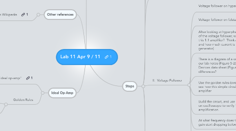
1. Steps
1.1. Github project https://github.com/stevekochscience/2012-Physics-308L-Lab-11-OpAmps
1.2. *** Op Amps are fairly robust, but still, be careful that connections are correct before plugging in the power supply ***
1.3. 1. First, before connecting the op amp circuit, make sure your power supply is working properly. Use multimeter to check for +5, +12, and -12 (+/- 1V)
1.4. 2. Check out the data sheet for the OP97-FP. Look at stuff you think is important. Look at the simplified schematic and locate transistors and other things you're familiar with
1.5. II. Voltage Follower
1.5.1. Voltage follower on hyperphysics
1.5.2. Voltage follower on falstad applet
1.5.3. After looking at hyperphsics, Falstad applet, and any other reading of the voltage follower, what seems to be the advantage of using this 1:1 amplifier? Think about how much current you can output and how much current is needed from the source (function generator)
1.5.4. There is a diagram of a voltage follower, both in our lab notes (Figure 5-2) and in the Analog Devices data sheet (Figure 5). Are there any differences?
1.5.5. Use the golden rules (over there on the left) to see how this simple circuit will be a 1:1 amplifier
1.5.6. Build the circuit, and use two channels on oscilloscope to verify 1:1 amplifiication.
1.5.7. At what frequency does the gain start dropping below 1?
1.5.7.1. Why does this matter?
1.5.8. Bonus (only do if you find it fun and would rather do this than some of the other op-amp circuits)
1.5.8.1. In last week's lab, in the "not not" circuit when we used an LED to light up the output of the logic gates, it actually drew substantial current and changed the logic value from +5V all the way down close to +2V. Luckily, +2 V was still high enough to turn on the next stage. How could you use a voltage follower to eliminate this problem? Try building it and verifying that you can use the voltage amplifier to turn on the light without affecting the logic value.
1.6. III. Summing Amplifier
1.6.1. OK, At this point I am getting bored by following this lab. There's no doubt that the sections in this lab are classic op-amp circuits which are useful to know. But you're not really going to remember them and you'll need a lot more practice to use op-amps in your own work or hobbies. So, I'm thinking that it would be much more useful for you to do the following: (A) Look up some op-amp circuits on the internet and find something that interests you, then build it. or (B) do the "bonus" from the last part of II above (this is what I want to do, since it's a real use of an op-amp for a purpose that we needed last week. or (C) follow the rest of the old lab manual (PDF). There's nothing wrong with any of these options, the point is to catch your own interest so you can learn a little bit.
1.6.2. If you do the Summing Amplifier, it's pretty easy to use the Golden Rules to calculate the ideal output of the op-amp.
1.6.3. A good thing to do with any of your op-amp circuits is to test their limits, especially in terms of frequency. If you build an amplifier, for example, you should be able to investigate the concept of "gain-bandwidth product"
1.7. *** AS ALWAYS, Keep an excellent notebook!!! ***
2. Notes
2.1. You can use either the Heathkit function generator or a separate function generator. I prefer the separate BK Precision, although you need to first set the correct amplitude (5 V bipolar / 10 V peak to peak)
2.2. Don't worry about all of the questions in the old lab manual. I don't even understand some of them at this point. Focus on gaining understanding and reading through our notes here. If you want to branch off on your own (for example last step of voltage follower), that is COMPLETELY FINE! Just make sure to take good notes!
3. Other references
3.1. Ideal Op-Amp on Wikipedia
4. Ideal Op-Amp
4.1. Read wikipedia "ideal op-amp"
4.2. Golden Rules
4.2.1. I. The output attempts to do whatever is necessary to make the voltage difference between the inputs zero.
4.2.2. II. The inputs draw no current.
