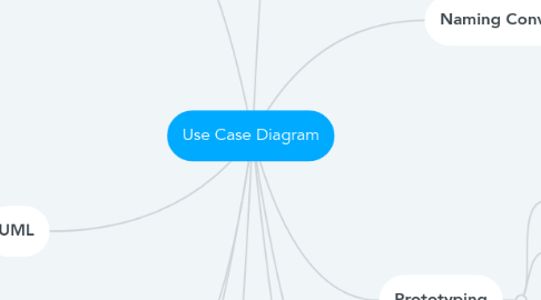
1. Relationships
1.1. Association
1.1.1. Line drawn between an actor and a use case.
1.1.2. Represents the communication link between an instance of the use case and an instance of the actor
1.2. <<include>>
1.2.1. Writing use cases can be repetitive at times
1.2.1.1. There are usually common steps/tasks across use cases of the same system.
1.2.2. Allows you to include the behaviour of one use case into the flow of another use case
1.2.3. Should not be used to create a hierarchical functional decomposition of the system.
1.2.4. Base use case MUST ALWAYS include the behaviour of the inclusion use case.
1.3. <<extend>>
1.3.1. Provides a way to insert new behaviour into an existing use case.
1.3.2. Extension use cases are generally not complete use cases and therefore cannot be triggered by an actor.
1.3.3. You can perceive extension use cases as OPTIONS that the system can branch to from the base use case.
1.3.4. Base use case has the option to call the extension use case.
1.4. Generalization
1.4.1. Shows that one actor can participate in all the associations with use cases that the more general actor can, plus some additional use cases
1.4.2. Shows that one use case provides all the functionality of the more general use case, and some additional functionality.
2. UML
2.1. A family of graphical notations that help in describing and designing software systems, particularly OO systems.
3. Use Case Descriptions
3.1. A simple paragraph to describe what the use case does.
3.1.1. What are the inputs and outputs?
3.1.2. What is recorded?
3.1.3. Are there any conditions to take note of?
3.2. For example, "Assign staff to work on a campaign".
3.2.1. This use case allows the campaign manager to record which staff are working on a particular campaign. A staff should not be assigned to work on more than two campaigns.
4. Purpose
4.1. To provide an overview of all or part of the usage requirements for a system
4.2. To communicate the scope of a project
4.3. To model the analysis of sage requirements in the form of a system use-case model
5. Use Cases
5.1. A use case is something that an actor wants the system to do.
5.1.1. Primarily Functional Requirement that indicate WHAT the system will do, not HOW to do it.
5.2. Identifying use cases
5.2.1. Find out what each actor wants to use the system for.
5.2.2. Helps to ask
5.2.2.1. What can the system do?
5.2.2.2. What does the actor want the system to do?
5.3. Use case modeling is iterative
5.3.1. You begin with just a name for a use case and fill the details later.
6. Actors
6.1. An actor specifies a role that some external entity adopts when interacting with the system DIRECTLY.
6.1.1. Primary Actor
6.1.1.1. A user role.
6.1.1.2. Actors are stakeholders who trigger the user cases
6.1.1.2.1. Customer triggers the "place order" use case
6.1.1.2.2. Student triggers the "book squash court" use case
6.1.1.2.3. Account holder triggers the "withdraw money" use case
6.1.2. Supporting Actor
6.1.2.1. A role played by another system, also known as external actors.
6.1.2.2. Actor that interacts with the use case after it has been triggered.
6.1.2.3. It is often a computer system that may be an organization or person that provides a server to the system
6.1.2.3.1. Credit card system that provides a server to the "place order" use case to authenticate the customer's credit card and make the necessary deduction
6.1.2.3.2. "print receipt" will use the Printer (supporting actor) to print the receipt.
7. Naming Conventions
7.1. Actors
7.1.1. Use a singular "noun" phrase
7.1.2. Start each word with an Uppercase letter
7.2. Use Cases
7.2.1. Start with a verb (represents the action) followed by some nouns (the object that the action is directed)
7.2.1.1. E.g. borrow item, return item, renew item
7.2.2. Use present tense for verb, do not use continuous tense
8. Prototyping
8.1. Use case modelling can be supported with prototyping.
8.2. Prototypes can be used to help elicit requirements.
8.3. Prototypes can be used to test out system architectures based on the use cases in order to meet the non-functional requirements.
8.4. Uses interface prototypes
8.4.1. Storyboarding can be used with hand-drawn designs.
8.4.2. Can be implemented using languages other than the one that the system will be developed in.
